I’m Tom Ballard — the Groundwater Guy — and in this step-by-step guide you’ll learn how to measure, interpret, and act on wire-to-water efficiency so you can make smarter decisions for your water infrastructure. If you manage wells, booster stations, or any pumping elements of your water infrastructure, this article walks you through the exact calculations, field steps, and operational strategies you need to convert electrical input into reliable hydraulic output more efficiently.

Step 1: Why Wire-to-Water Efficiency Matters for Your Water Infrastructure
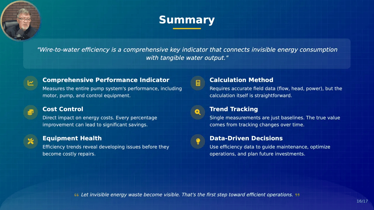
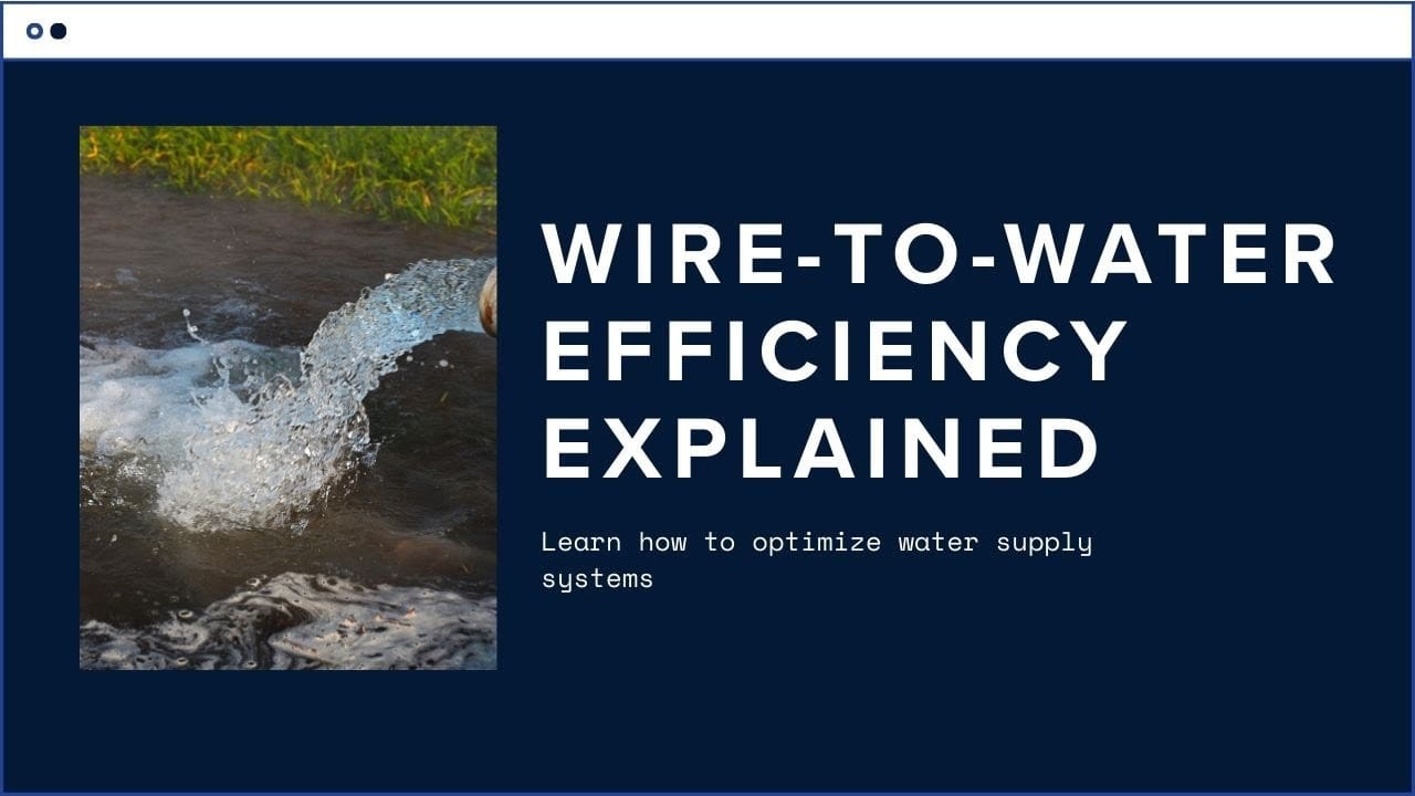
Wire-to-water efficiency is the single metric that links the electricity you buy to the gallons you deliver. For any water infrastructure operator, it is the clearest way to see if your pumps and motors are wasting energy or performing as designed. If you want to control costs, extend equipment life, reduce carbon footprint, and make data-driven decisions, measuring wire-to-water efficiency is where you start.
Think of your pumps and motors as the heart of your water infrastructure. When efficiency drops, energy bills climb and maintenance needs multiply. When you track this efficiency over time, you can detect wear and tear early, prioritize maintenance, and avoid emergency replacements that disrupt service. For water infrastructure systems that operate continuously or at peak times, even a small percentage improvement in wire-to-water efficiency translates into significant savings.
Step 2: Understand the Core Formula (What You Must Measure)
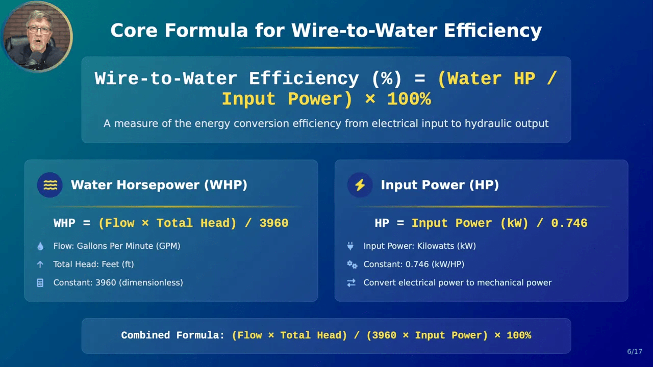
The core formula you need is simple in structure:
- Wire-to-water efficiency (%) = (Water horsepower / Input horsepower) × 100
Water horsepower (WHP) is the hydraulic power being delivered by the pump, calculated as:
- WHP = (Flow (gpm) × Total Dynamic Head (ft)) / 3960
Input horsepower is the electrical power supplied to the motor, converted to mechanical horsepower by dividing kilowatts by 0.746. Getting accurate measurements of flow, head, and electrical power is critical — garbage in, garbage out.
Step 3: Gather the Right Field Data for Your Water Infrastructure
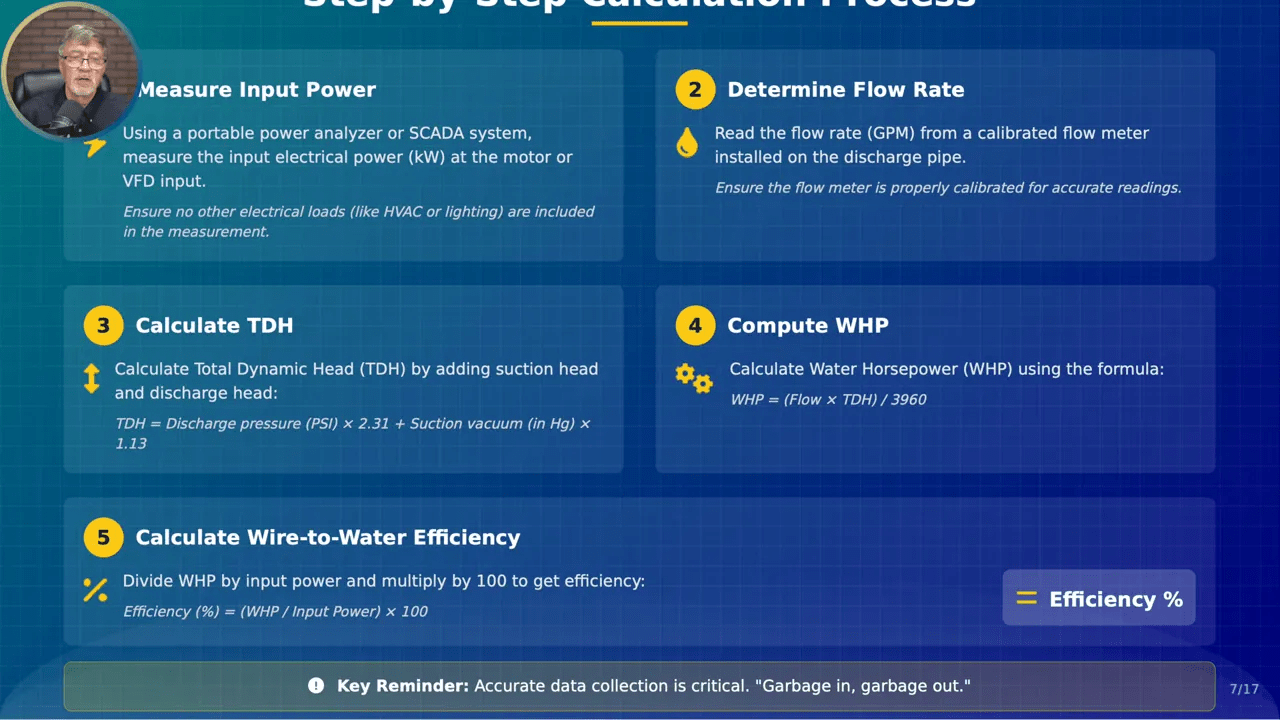
Before you run any numbers, you must collect accurate field data. Follow these measurement rules for reliable results:
- Measure input electrical power (kW) at the motor or VFD input using a portable power analyzer or SCADA. Make sure the meter is on the line side of the VFD, not the load side, and that the reading excludes unrelated electrical loads such as lighting or HVAC.
- Measure flow (gpm) with a calibrated flow meter on the discharge pipe. Confirm calibration dates and verify proper installation orientation and straight-run requirements.
- Measure pressures for Total Dynamic Head (TDH): discharge pressure (psi) and suction vacuum (inches Hg) for well pumps. Convert pressure to feet of head using conversion factors shown below.
- Allow the pump to run at stable operation for 15 minutes before recording values, and take at least three repeatable readings at each test point.
For most water infrastructure systems, good instrumentation and adherence to test protocols will remove a lot of uncertainty and provide a solid baseline. Talk to your operators — they can often point out irregularities or recurring problems you should document during testing.
Step 4: Calculate Total Dynamic Head (TDH) — The Most Common Mistake
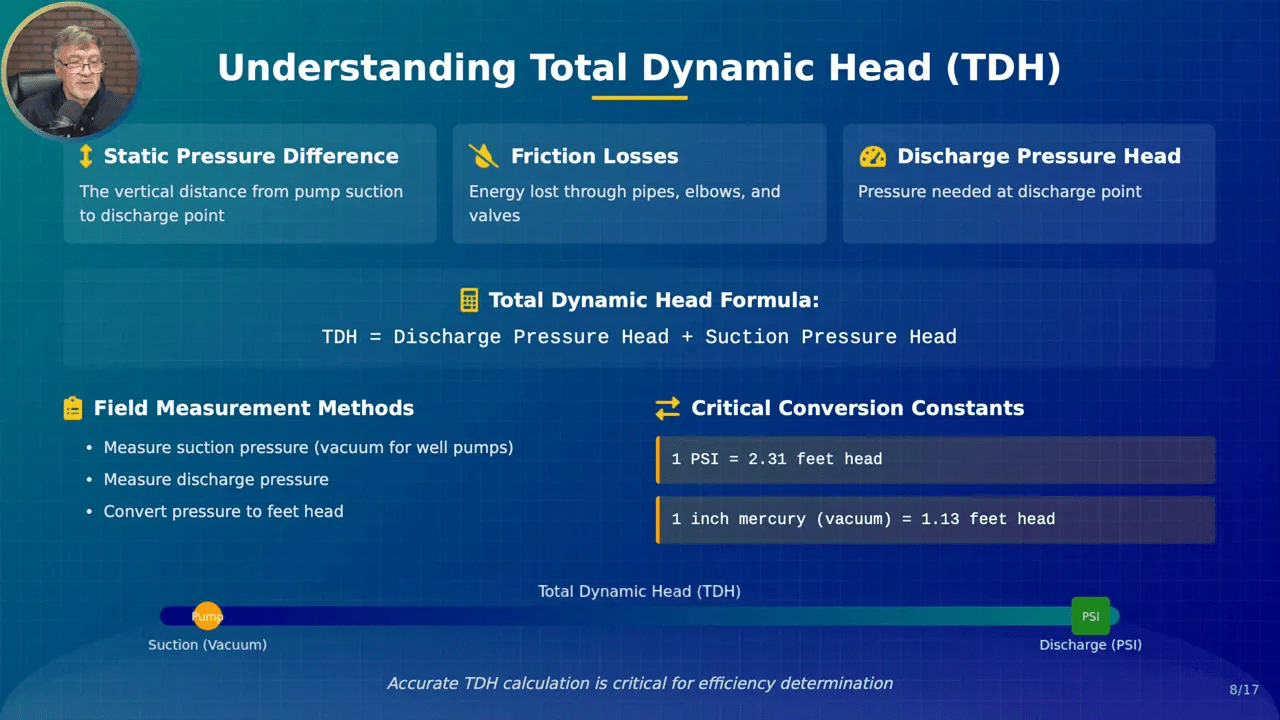
Total Dynamic Head is the sum of all static and dynamic components that the pump must overcome. TDH includes elevation, discharge pressure, suction pressure (or vacuum for wells), and pipe friction losses. For practical field testing you typically calculate TDH as:
- TDH (ft) = (Discharge pressure (psi) × 2.31) + (Suction vacuum (inches Hg) × 1.13)
Key conversions to remember:
- 1 psi = 2.31 feet of head
- 1 inch of mercury (in Hg) = 1.13 feet of head
Many operators use an air tube or pressure tap to read the static column and get a continuous measurement of discharge pressure, which is handy for automated trend tracking in your water infrastructure management system. Accurate TDH is critical — an error in head translates directly into an error in WHP and therefore in efficiency.
Step 5: Compute Water Horsepower and Wire-to-Water Efficiency
Once you have flow and TDH, compute water horsepower:
- WHP = (Flow (gpm) × TDH (ft)) / 3960
Then convert measured electrical input to horsepower:
- Input HP = Input power (kW) / 0.746
Finally, compute wire-to-water efficiency:
- Efficiency (%) = (WHP / Input HP) × 100
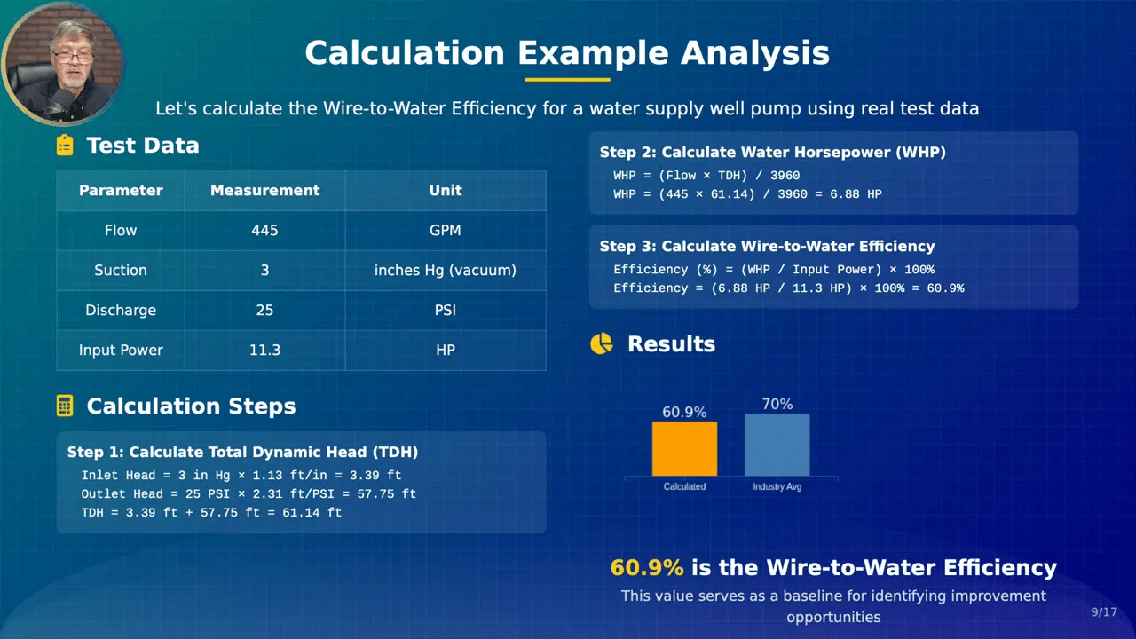
Let’s walk through a concise example for your water infrastructure: If the flow is 445 gpm, suction 3 in Hg, discharge 25 psi, and measured input power converts to 11.3 HP, then:
- Suction head = 3 in Hg × 1.13 = 3.39 ft
- Discharge head = 25 psi × 2.31 = 57.75 ft
- TDH = 3.39 + 57.75 = 61.14 ft
- WHP = (445 × 61.14) / 3960 = 6.88 HP
- Efficiency = (6.88 / 11.3) × 100 = 60.9%
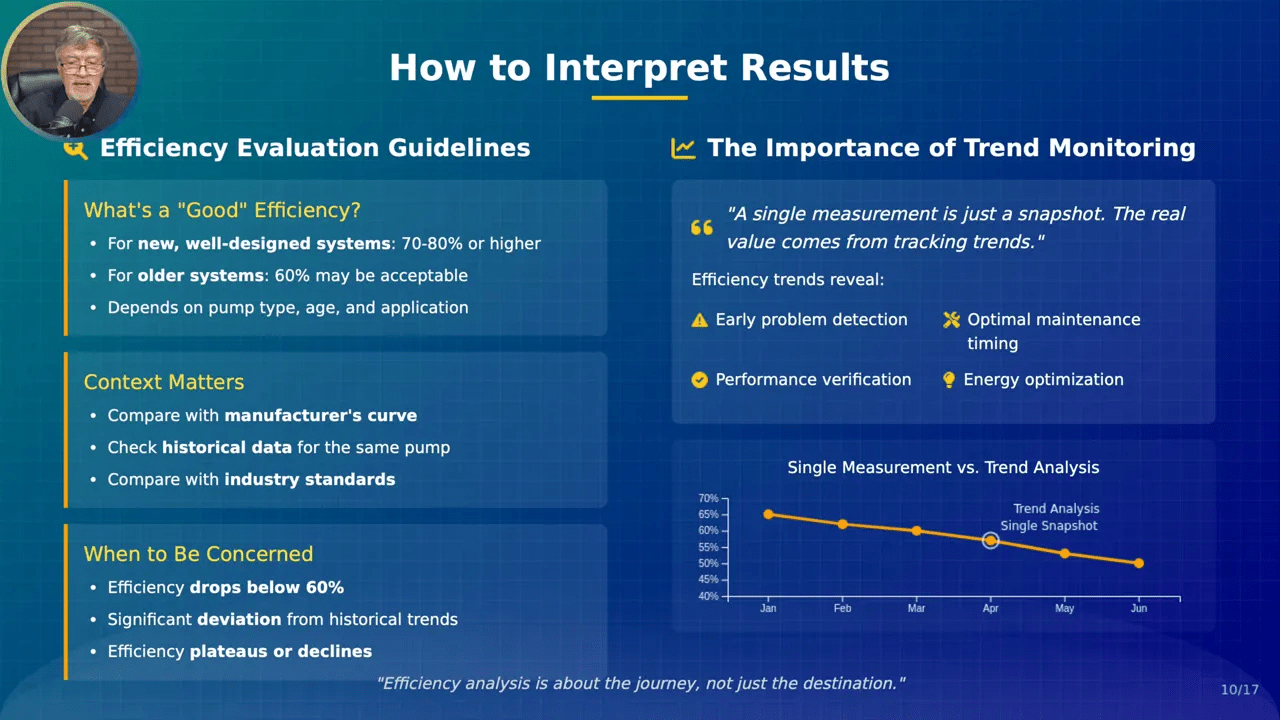
That 60.9% number gives you a snapshot of how well that pump-motor-VFD combination is converting your purchased electricity into water. For water infrastructure systems a wire-to-water efficiency of roughly 60–80% is common; new, well-matched systems often sit nearer 70–80%, while older or mismatched equipment can be lower.

Step 6: Interpret Results — What Numbers Should Trigger Your Attention?
When you start recording efficiencies across your water infrastructure, you’ll begin to see patterns. Use these rules of thumb to prioritize action:
- If wire-to-water efficiency falls below ~60%, investigate promptly — this often indicates wear, cavitation, clogged intakes, or a mismatch between pump and system.
- If efficiency deviates significantly from the manufacturer’s published curve for that pump, the pump may be operating off its best efficiency point (BEP) or suffering mechanical degradation.
- Single measurements are useful for a snapshot, but trends are where the value is. A steady decline over months is a red flag even if current efficiency is marginally acceptable.
Remember that wire-to-water efficiency is multiplicative across components (not an average). If the motor is 92% efficient and the pump is 75% efficient, your combined wire-to-water efficiency will be roughly 0.92 × 0.75 = 0.69 (69%). Don’t average efficiencies — multiply them. That subtle distinction saves you from overestimating your system’s performance and underestimating savings potential in your water infrastructure.
Step 7: Track Trends — Turn Snapshots into Predictive Insight
Track wire-to-water efficiency over time in a simple monitoring log so your water infrastructure program becomes predictive rather than reactive. Your log should include date, pump ID, flow, TDH, input power, calculated efficiency, and recommended action. This data becomes the heartbeat of an asset management plan.
Benefits of consistent trend tracking for water infrastructure include:
- Early problem detection — efficiency declines often appear before catastrophic failure.
- Optimized maintenance scheduling — you can shift from calendar-based to condition-based maintenance.
- Long-term energy optimization — identifying pumps that are energy hogs and making strategic upgrades yields direct operational savings.
- Performance verification — confirm after maintenance or upgrades that the system returned to expected efficiency.
Every percentage point of improvement in wire-to-water efficiency reduces energy consumption and operating costs across your water infrastructure. Use trend lines to forecast when efficiency will breach action thresholds and schedule interventions in advance.
Step 8: Prioritize Which Pumps to Test in Your Water Infrastructure
Testing every single pump in a large network may be impractical. Prioritize testing effort where it will matter most for your water infrastructure:
- Pumps with long runtimes or continuous duty (24/7).
- Pumps with frequent repairs or chronic maintenance problems.
- High-power pumps (e.g., >40 HP) where efficiency gains pay dividends quickly.
- Critical-task pumps whose failure would cause major system impacts.
Use a simple risk-based approach that considers both likelihood of failure and consequence of failure. Testing pumps with the highest combined risk will deliver the best ROI across your water infrastructure.
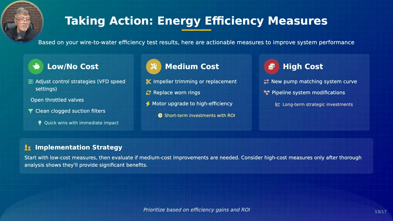
Step 9: Take Action — Low, Medium, and High-Cost Efficiency Measures
Once you’ve identified underperforming pumps in your water infrastructure, plan corrective actions using a cost-tiered approach:
- Low-cost / No-cost: Adjust control strategies, tune VFD speed ranges, open throttled valves, and clean plugged suction screens. These quick wins often restore a noticeable share of lost efficiency.
- Medium-cost: Impeller trimming, replace worn wear rings, or upgrade motors to high-efficiency models. These yield reliable improvements with reasonable payback periods.
- Higher-cost / Strategic: Replace pumps or select a new pump matched to the system curve and duty point; redesign piping or install better control schemes. These are capital projects but can transform the energy profile of your water infrastructure.
Start with low-cost measures to capture immediate savings, then evaluate medium-cost fixes. Reserve major capital changes for situations where the data indicates a clear return on investment. The data from your wire-to-water efficiency logs will justify funding and help you sequence improvements across your water infrastructure.
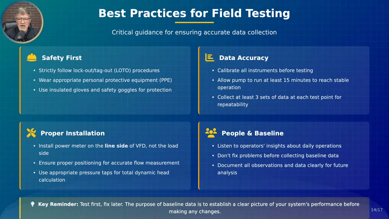
Step 10: Field Testing Best Practices to Keep Your Water Infrastructure Data Reliable
Follow these field testing protocols to make sure the measurements you collect across your water infrastructure are trustworthy and repeatable:
- Safety first: always use lockout-tagout and appropriate PPE (insulated gloves, eye protection).
- Calibrate instruments before testing — flow meters, pressure transducers, and power analyzers.
- Let the pump stabilize for at least 15 minutes at the test point before recording data.
- Take at least three consistent readings per test point and document any anomalies.
- Install the power meter on the line side of the VFD; avoid mixing other electrical loads in the measurement.
- Document operator observations and any external factors (e.g., wells with low water level, debris screens partially blocked).
Do not fix suspected problems before you collect baseline data. Baseline data lets you quantify the problem and evaluate improvement after repairs. Test first, fix later — this is the data-driven approach that improves the outcomes of your water infrastructure investments.
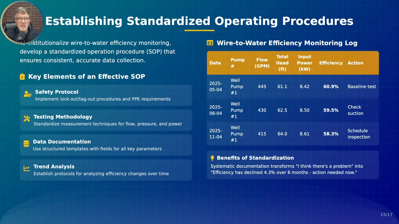
Step 11: Institutionalize Monitoring — SOPs and Logs for Your Water Infrastructure
To make wire-to-water efficiency part of everyday operations, create a Standard Operating Procedure (SOP) that covers:
- Safety requirements and lockout-tagout.
- Instrumentation and calibration checks.
- Testing methodology and required stabilization times.
- Data recording templates and monitoring logs.
- Frequency of testing and thresholds for corrective action.
An SOP ensures consistency so the trends you collect are comparable over time. Once you institutionalize monitoring into your water infrastructure program, the data becomes a reliable guide to prioritization and budgeting. A simple monitoring log that feeds into asset management software can convert a recurring 4.3% decline into an actionable maintenance task before major failure occurs.
Step 12: Use Energy Intensity to Compare and Justify Investments Across Your Water Infrastructure
Beyond wire-to-water efficiency, calculate energy intensity to compare pumps and stations across your water infrastructure network:
- Energy intensity = kWh per million gallons (or kWh per 1000 gallons) = Monthly electricity / Monthly delivered volume
This metric identifies which pumps or stations are energy hogs and helps quantify potential savings from upgrades. It’s especially useful when presenting improvement projects to managers or boards because it converts technical performance into an operational cost figure.
When you combine energy intensity with wire-to-water efficiency trends, you can prioritize projects that yield the biggest savings per dollar invested — a practical way to stretch capital dollars in a constrained budget environment for your water infrastructure.
Quick Checklist You Can Use Today
- Install reliable metering: flow, pressure, and electrical input on every critical pump.
- Develop an SOP and monitoring log for wire-to-water testing and trend recording.
- Start with low-cost actions to capture quick savings across your water infrastructure.
- Scale to medium and high-cost investments only when data shows clear ROI.
- Use trend analysis to shift from reactive to predictive maintenance.
Adopting these steps will help your water infrastructure become more efficient, resilient, and cost-effective.
Conclusion: Make Wire-to-Water Efficiency the Backbone of Your Water Infrastructure Strategy
Wire-to-water efficiency ties invisible electricity consumption to tangible water output. For any water infrastructure manager, it is the most actionable metric for lowering energy costs, extending equipment life, and improving system reliability. Follow the step-by-step approach in this guide — measure accurately, calculate precisely, track trends, prioritize testing, and take tiered actions — and you’ll convert data into savings and improved service.
If you implement a disciplined program to measure and trend wire-to-water efficiency, you’ll transform decision-making for your water infrastructure from guesswork to evidence-based planning. Over time, those small percentage improvements will compound into meaningful operating savings, fewer emergency repairs, and a healthier asset base.
If you have questions about setting up metering, calculating TDH, or building an SOP tailored to your utility, reach out — I review comments and help utilities adopt data-driven practices every day. Make wire-to-water efficiency the heart of your water infrastructure program and watch the benefits follow.