This practical guide is based on a field study presented by The Groundwater Guy and shows you how to locate prospect water supply wells in Virginia’s Blue Ridge using fracture trace and lineament assessment (FTLA) coupled with hydrostratigraphic analysis. If you are planning improvements to water infrastructure for a small utility or community, this step-by-step tutorial will walk you through the methods, decision criteria, and construction recommendations we used in Floyd County, Virginia.
Step 1: Define your study area and objectives
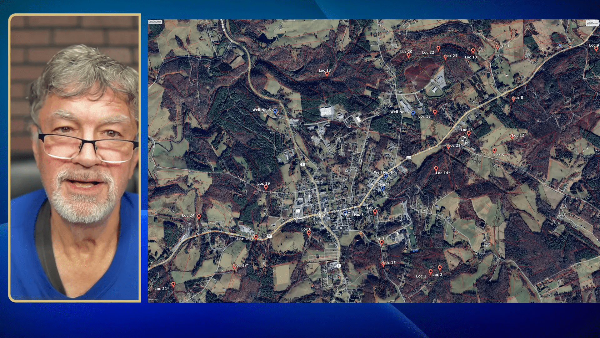
Begin by clearly defining the geographic bounds of your project and the operational objectives for the water infrastructure you will support. In our study the area was centered on the town of Floyd in Floyd County — a roughly two-mile radius rectangle around the town on the Blue Ridge crest. Your objectives should include target yields, preferred well depths, and operational constraints such as proximity to existing wells, available power, and land ownership.
- Define the municipal or utility needs (peak demand, redundancy).
- Map existing water infrastructure and known well locations to avoid interference.
- Establish acceptable ranges for drilling depth and diameter based on cost and yield expectations.
Step 2: Assemble geology, topography, and remote-sensing datasets
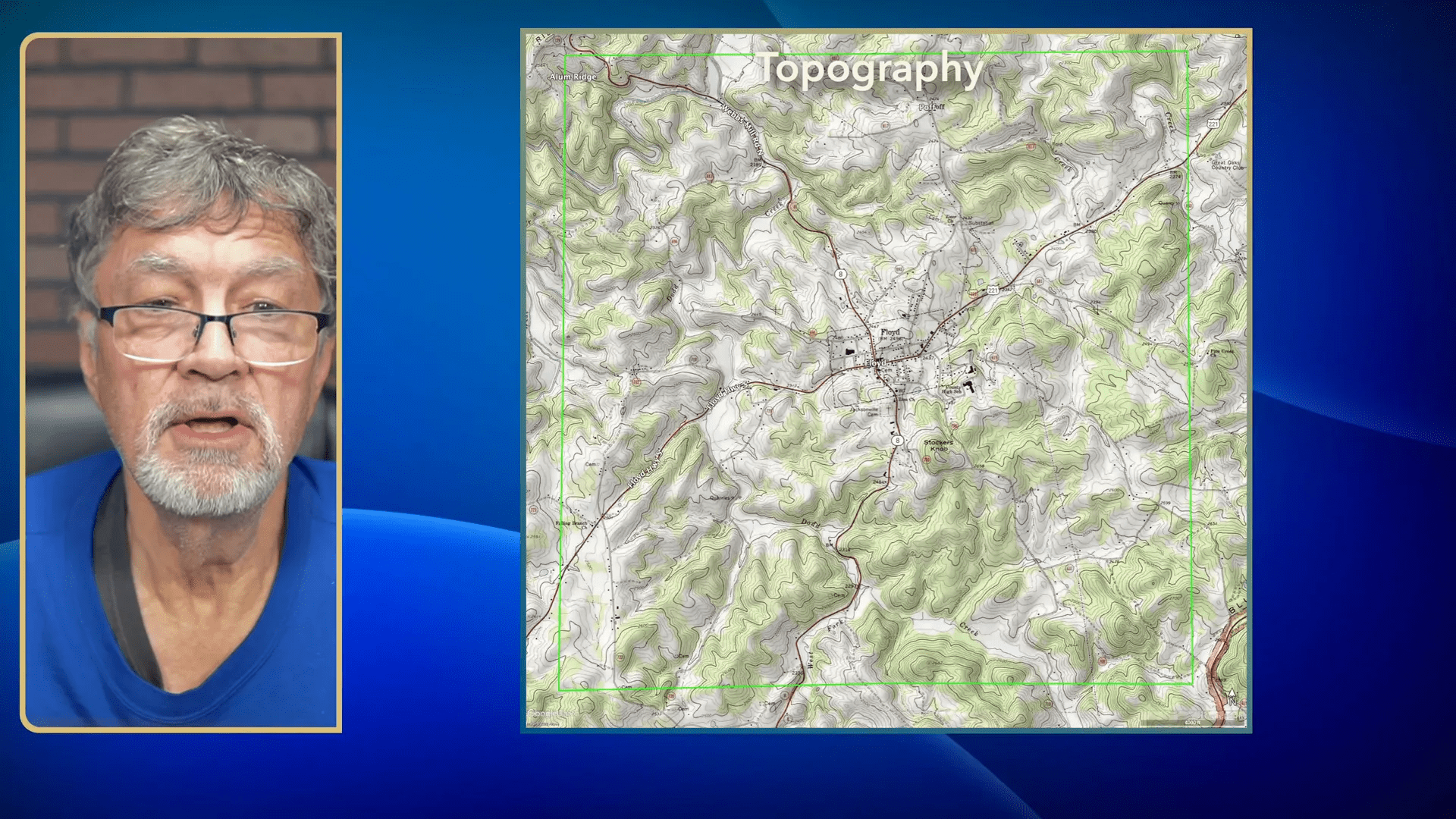
Collect the datasets you need to identify structural controls on groundwater. For fractured bedrock environments you will rely on structural and lithologic maps, LiDAR, satellite imagery, aerial photos, topographic maps, and digital elevation models (DEMs). These help you identify lineaments that represent bedrock fractures and faults, and allow you to overlay lithology to discern which rock units are likely to host productive fractures.
- Geologic maps: locate thrusts, folds, and lithologic units (e.g., amphibolite, biotite gneiss, schist).
- LiDAR/DEM: identify subtle linear valleys, aligned ridges, or scarps that coincide with fractures.
- Satellite imagery/aerial photos: trace vegetative or soil-moisture contrasts that follow fractures.
- Existing well records: note production zones and depths when available.
Step 3: Identify fracture traces (FTLA) and interpret lineaments
Perform a fracture trace and lineament assessment (FTLA). Map linear features across multiple datasets and then critically filter out anthropogenic or non-fracture linears (roads, fences, property boundaries). Your goal is to identify natural linears that likely represent open fractures or zones of concentrated fracturing.
- Digitally trace linear features visible on LiDAR and imagery.
- Cross-check linears on topography and geology layers—true fractures will often align with changes in drainage patterns or slope.
- Eliminate cultural features (roads, powerlines) that mimick linear signatures.
In metamorphic bedrock you are not relying on primary porosity; instead the secondary porosity created by fractures controls groundwater storage and flow. Prioritize lineaments that cross-cut lithologic contacts or run parallel to mapped thrusts and faults.
Step 4: Couple FTLA with hydrostratigraphic analysis
FTLA alone identifies structural targets; hydrostratigraphic analysis tells you whether the bedrock unit hosting those fractures will behave as a good aquifer. Map lithologic units and classify them by their propensity to fracture and hold transmissive openings.
- Label units that are likely to fracture and create transmissive networks (e.g., amphibolite, competent gneiss).
- Avoid units that tend to deform by slippage rather than fracturing (e.g., schist), unless contacts or shear zones are present.
- Prioritize fracture intersections within favorable hydrostratigraphic units — intersections commonly yield better production than single isolated fractures.
Example: In our Floyd study amphibolite in the hanging wall of an east-northeast trending thrust was identified as a preferred hydrostratigraphic unit because it tends to develop open, transmissive fractures compared with adjacent biotite gneiss or schist.
Step 5: Apply conceptual models and depth considerations
Use a conceptual groundwater model for fractured rock: most groundwater in such settings is stored and transmitted in an interconnected network of fractures and weathered bedrock. Consider the following principles:
- Interconnected fractures are required to sustain aquifer conditions — isolated fractures give limited yield.
- Fracture density normally decreases with depth because lithostatic pressure tends to close fractures below ~300–400 ft.
- Thrust faults, fault hanging walls, and contact zones often concentrate fractures and can be prime targets.
Empirical data for Floyd County supports a clear trend: yields decrease significantly below roughly 400 ft. While you may occasionally encounter deep conductive fractures, plan drilling with the expectation that most productive zones will be within the upper 400–600 ft.
Step 6: Define target criteria and rank prospects
Translate your analysis into concrete selection rules for well siting. Our project used these primary criteria:
- Two or more fracture intersections within the target depth window.
- Fracture intersections located within amphibolite (or otherwise favorable hydrostratigraphic units).
- Target depth generally less than 600 ft, ideally near or above 400 ft.
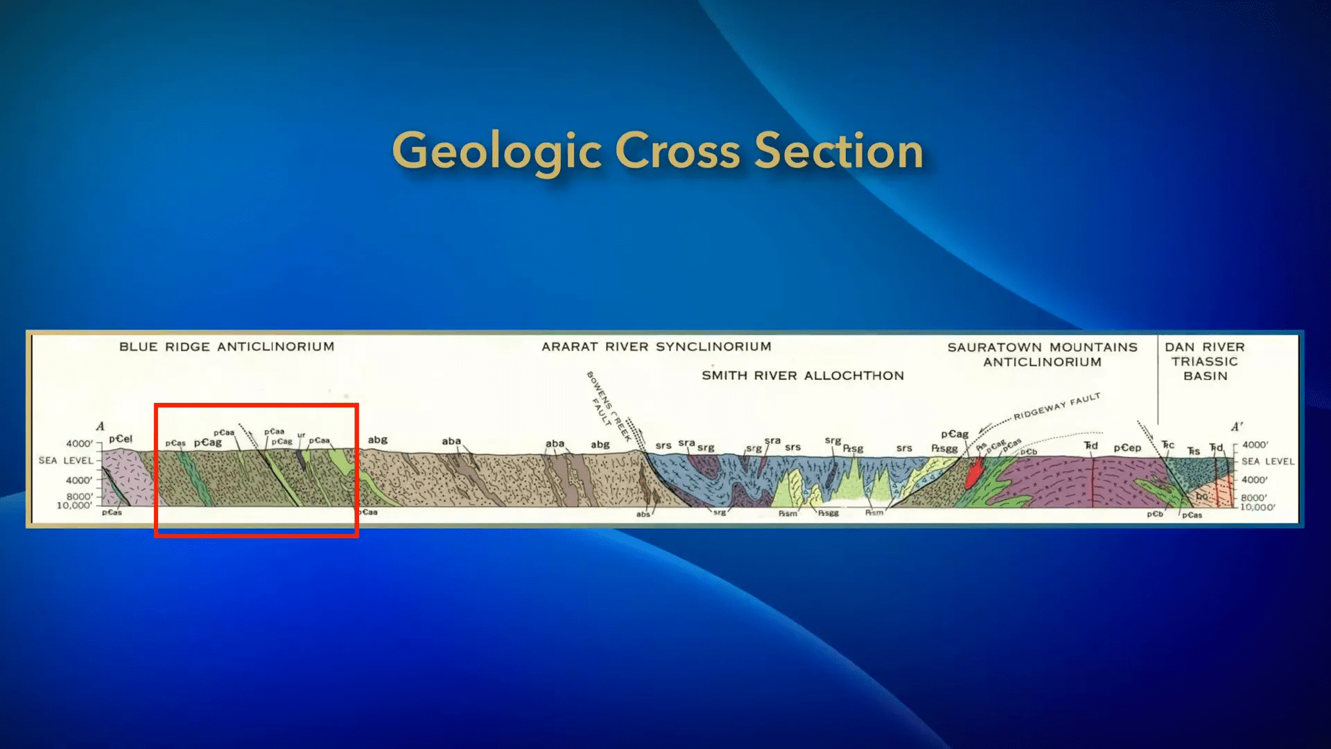
These rules produced an initial set of ~24 candidate locations. Rank candidates by fracture intersection density, lithology, proximity to known productive wells, and ease of access for infrastructure.
Step 7: Overlay real-world constraints — infrastructure, ownership, and environment
Reality often forces compromises. You must overlay practical constraints onto your ranked geologic targets:
- Power availability: can you energize a pump at the proposed site?
- Land ownership and access: are easements or purchases required?
- Proximity to existing utility piping and treatment facilities to minimize extension costs.
- Environmental constraints (wetlands, protected areas) and permitting considerations.
After applying these constraints, you will likely narrow your list to a smaller set of final candidate sites that balance hydrogeologic potential with operational feasibility.
Step 8: Recommend drilling and construction specifications
Provide the utility with clear, conservative construction recommendations. For small water utilities in fractured bedrock like the Floyd PSA we recommended:
- Target depth: 400–600 ft to maximize chances of intersecting multiple productive fractures while avoiding depth-related closure of fractures.
- Avoid drilling shallower than ~300 ft in areas prone to summer drought, as shallower wells risk seasonal depletion.
- Avoid excessive depth (>800 ft) unless structural evidence indicates deep open fractures — below these depths fracture permeability commonly drops.
- Well diameter: at least 10 in for municipal supply wells to accommodate larger pumps and rehabilitation work.
Example of expected production: one Floyd well (constructed 2005) encountered a 3-foot productive fracture and produced roughly 160 gallons per minute. Multiple fracture intersections historically produced multiple productive zones in older wells constructed in the 1979–1989 window.
Step 9: Deliver the study, monitor outcomes, and adapt
Submit the recommended sites and construction specifications to the utility, then support the drilling program with observation and data collection. After drilling, update your models using actual well logs, pump tests, and production records. Use this feedback loop to refine future siting and to inform ongoing water infrastructure planning.
- Collect detailed well logs (fracture intercepts, casing, grout, static water levels).
- Perform step-drawdown and constant-rate pump tests to establish sustainable yields.
- Record water quality and temperature profiles to infer flow paths.
Quick checklist for your water infrastructure well-siting study
- Define study area and objectives.
- Assemble geology, LiDAR, and imagery datasets.
- Map and validate fracture traces (FTLA).
- Overlay hydrostratigraphy and prioritize amphibolite/competent units.
- Target fracture intersections (≥2 intersections preferred).
- Plan drilling depth (target 400–600 ft; avoid >800 ft unless justified).
- Specify well diameter ≥10 in for utility wells.
- Incorporate power, ownership, and environmental constraints.
- Monitor drilled wells and adapt the model.
By following these steps you will significantly increase the probability of siting productive wells that support reliable water infrastructure for a small utility or community. The combined approach — FTLA plus hydrostratigraphic analysis — is especially valuable in fractured bedrock provinces like the Blue Ridge where secondary porosity controls groundwater availability.
For more in-depth resources, refer to the Southeast Hydrogeology materials and hydrostratigraphic references cited in the original study. If you are advising a utility, include a data collection plan to capture well logs and pump test results immediately after drilling — that information is critical for continually improving your water infrastructure decisions.
Author note: This guide summarizes the methods used in a well location study presented by The Groundwater Guy for Floyd County, Virginia. Use the steps above to structure your own FTLA plus hydrostratigraphic program to support practical, cost-effective water infrastructure development.